When we start school as young children, one of the first lessons we learn is how to share (followed quickly by not running with scissors). As our Sr. Director of Systems Engineering, Kent Orthner, discussed at DAC this past June, sharing is also key when it comes to closing timing with embedded FPGAs (eFPGAs). With an eFPGA such as Speedcore IP, the task of closing timing is owned by two people: the ASIC designer, responsible for the design in the host ASIC, and the FPGA designer, responsible for the design targeting the FPGA. This situation is very analogous to how timing is closed on a PCB with an FPGA, where both designers need to cooperate and share the timing arc (and the FPGA design may change long after the board design is complete).
With an eFPGA, the programmable block may be inserted anywhere inside an ASIC, meaning that the individual eFPGA ports may connect to other blocks within the ASIC, or to buffers connecting to external pins. Further complicating the process is the fact that the design host in the eFPGA can and will change over time, possibly years after the ASIC was designed.
But rather than leaving it to design teams to develop a process, Achronix provides a defined methodology for achieving timing closure as well as support for industry-standard timing analysis tools. As Kent explained (video of his talk is here), there are two timing models (or modes) available to the design team: simple and advanced.
Simple Mode
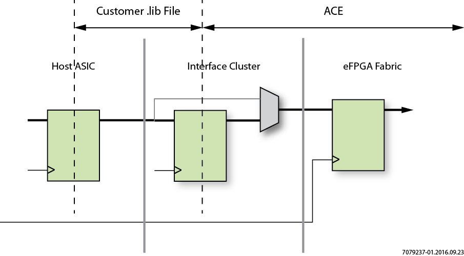
In the simple timing mode, the timing between IP in the host ASIC outside the Speedcore instance terminates at the register in the interface cluster in the Speedcore boundary ring (show below). In this scenario, delays are not dependent on the design hosted in the Speedcore instance. With simple mode, timing closure is performed by the SoC supplier using standard tools (e.g. PrimeTime) where the .lib files represents timing data (setup/hold/clock-to-q) to/from boundary flip-flops. ACE design tools may require clock insertion delay information in this scenario.
Advanced Mode
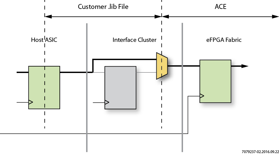
As the name implies, this scenario is more complex, with timing closure between the Speedcore eFPGA and the IP outside is shared between the SoC supplier (e.g. PrimeTime) and ACE design tools (shown below). With advanced mode, the .lib files do not contain delays to a specific flip-flop in the Speedcore fabric, but rather represent a range of flip-flops, chosen such that timing closure using the hardware .lib files correlate to timing closure in ACE. The .lib files still contain one setup/hold/clk-to-q value for each pin. In this mode, final timing sign-off comes from ACE, completed by using a suite of user designs containing critical paths representative of actual end-user designs.
Timing Closure is an Iterative Process
As Kent explains, timing closure consists of basic set of steps:
- Choose a target frequency and, determine how much of the clock cycle will be used by (shared with) the ASIC logic.
- Run ASIC timing closure using an industry-standard tool (e.g., PrimeTime) with the Achronix-provided budgetary
.libfiles. - Extract the ASIC portion of the delays on each wire and provide them to ACE via constraint files, following the template provided by Achronix.
- Run a suite of representative designs through ACE to confirm that timing closure has been met for each one.
- If timing cannot be met for one or more of these designs, modify the FPGA design or return to step 1 .
The bonus is that the selection of timing mode does not need to be made at the time the ASIC is designed — the decision is left up the FPGA designer. To learn more, view Kent's video.